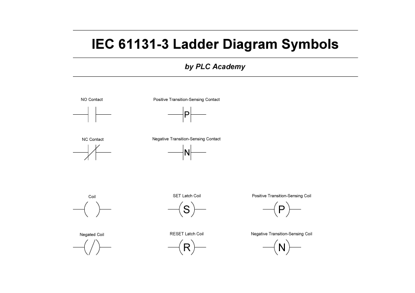
Ladder Diagram Relay Symbol . Ladder diagrams differ from regular schematic diagrams of the sort common to electronics. a very common form of schematic diagram showing the interconnection of relays to perform these functions is called a ladder diagram. the ladder diagram uses contacts to represent the switches, or any input, and the coil symbol to represent an output. In a “ladder” diagram, the. The coil symbol is usually accompanied by a label indicating the specific output it controls. ladder logic symbols are a set of symbols used in plc ladder diagrams. They are called “ladder” diagrams because they are constructed in a way that resembles a ladder with two vertical rails and rungs between them. these diagrams documented how connections between devices were made on relay panels; The coil symbol resembles a circle or an oval shape and represents an output.
from guidelibperplexing.z13.web.core.windows.net
The coil symbol resembles a circle or an oval shape and represents an output. In a “ladder” diagram, the. ladder logic symbols are a set of symbols used in plc ladder diagrams. the ladder diagram uses contacts to represent the switches, or any input, and the coil symbol to represent an output. Ladder diagrams differ from regular schematic diagrams of the sort common to electronics. a very common form of schematic diagram showing the interconnection of relays to perform these functions is called a ladder diagram. The coil symbol is usually accompanied by a label indicating the specific output it controls. these diagrams documented how connections between devices were made on relay panels; They are called “ladder” diagrams because they are constructed in a way that resembles a ladder with two vertical rails and rungs between them.
Relay Logic Diagram Symbols
Ladder Diagram Relay Symbol They are called “ladder” diagrams because they are constructed in a way that resembles a ladder with two vertical rails and rungs between them. these diagrams documented how connections between devices were made on relay panels; The coil symbol resembles a circle or an oval shape and represents an output. In a “ladder” diagram, the. Ladder diagrams differ from regular schematic diagrams of the sort common to electronics. a very common form of schematic diagram showing the interconnection of relays to perform these functions is called a ladder diagram. the ladder diagram uses contacts to represent the switches, or any input, and the coil symbol to represent an output. The coil symbol is usually accompanied by a label indicating the specific output it controls. ladder logic symbols are a set of symbols used in plc ladder diagrams. They are called “ladder” diagrams because they are constructed in a way that resembles a ladder with two vertical rails and rungs between them.
From instrumentationtools.com
Introduction to PLC Ladder Diagrams Free PLC Tutorials Download Ladder Diagram Relay Symbol Ladder diagrams differ from regular schematic diagrams of the sort common to electronics. In a “ladder” diagram, the. The coil symbol is usually accompanied by a label indicating the specific output it controls. these diagrams documented how connections between devices were made on relay panels; ladder logic symbols are a set of symbols used in plc ladder diagrams.. Ladder Diagram Relay Symbol.
From wiring10.blogspot.com
Ladder Wiring Diagram Symbols / Ladder Logic Symbols Schematic Ladder Diagram Relay Symbol ladder logic symbols are a set of symbols used in plc ladder diagrams. the ladder diagram uses contacts to represent the switches, or any input, and the coil symbol to represent an output. In a “ladder” diagram, the. They are called “ladder” diagrams because they are constructed in a way that resembles a ladder with two vertical rails. Ladder Diagram Relay Symbol.
From www.circuitdiagram.co
Circuit Diagram Relay Symbol Circuit Diagram Ladder Diagram Relay Symbol The coil symbol is usually accompanied by a label indicating the specific output it controls. Ladder diagrams differ from regular schematic diagrams of the sort common to electronics. ladder logic symbols are a set of symbols used in plc ladder diagrams. The coil symbol resembles a circle or an oval shape and represents an output. In a “ladder” diagram,. Ladder Diagram Relay Symbol.
From wiringdbshouffchoibss.z14.web.core.windows.net
Relay Logic Wiring Diagrams Ladder Diagram Relay Symbol Ladder diagrams differ from regular schematic diagrams of the sort common to electronics. They are called “ladder” diagrams because they are constructed in a way that resembles a ladder with two vertical rails and rungs between them. these diagrams documented how connections between devices were made on relay panels; In a “ladder” diagram, the. a very common form. Ladder Diagram Relay Symbol.
From circuitwiringnears88.z22.web.core.windows.net
Relay Ladder Diagram Ladder Diagram Relay Symbol ladder logic symbols are a set of symbols used in plc ladder diagrams. They are called “ladder” diagrams because they are constructed in a way that resembles a ladder with two vertical rails and rungs between them. the ladder diagram uses contacts to represent the switches, or any input, and the coil symbol to represent an output. The. Ladder Diagram Relay Symbol.
From in.pinterest.com
Ladder Diagram Symbols Ladder logic, Diagram, Logic Ladder Diagram Relay Symbol The coil symbol is usually accompanied by a label indicating the specific output it controls. these diagrams documented how connections between devices were made on relay panels; They are called “ladder” diagrams because they are constructed in a way that resembles a ladder with two vertical rails and rungs between them. The coil symbol resembles a circle or an. Ladder Diagram Relay Symbol.
From diagramofwiring.blogspot.com
Motor Control Ladder Diagram Symbols Electrical Wiring Ladder Diagram Relay Symbol In a “ladder” diagram, the. The coil symbol is usually accompanied by a label indicating the specific output it controls. a very common form of schematic diagram showing the interconnection of relays to perform these functions is called a ladder diagram. ladder logic symbols are a set of symbols used in plc ladder diagrams. the ladder diagram. Ladder Diagram Relay Symbol.
From www.allaboutcircuits.com
Switches, Electrically Actuated (Relays) Circuit Schematic Symbols Ladder Diagram Relay Symbol the ladder diagram uses contacts to represent the switches, or any input, and the coil symbol to represent an output. In a “ladder” diagram, the. these diagrams documented how connections between devices were made on relay panels; The coil symbol resembles a circle or an oval shape and represents an output. a very common form of schematic. Ladder Diagram Relay Symbol.
From www.scribd.com
80jicstandardgraphicsymbolsforelectricalladderdiagrams.pdf Ladder Diagram Relay Symbol The coil symbol is usually accompanied by a label indicating the specific output it controls. these diagrams documented how connections between devices were made on relay panels; the ladder diagram uses contacts to represent the switches, or any input, and the coil symbol to represent an output. Ladder diagrams differ from regular schematic diagrams of the sort common. Ladder Diagram Relay Symbol.
From www.realpars.com
A Beginner's Guide to PLC Programming using Ladder Diagram, Function Ladder Diagram Relay Symbol The coil symbol resembles a circle or an oval shape and represents an output. the ladder diagram uses contacts to represent the switches, or any input, and the coil symbol to represent an output. ladder logic symbols are a set of symbols used in plc ladder diagrams. a very common form of schematic diagram showing the interconnection. Ladder Diagram Relay Symbol.
From circuitdiagramdivs.z21.web.core.windows.net
Plc Ladder Diagram Symbols Chart Ladder Diagram Relay Symbol The coil symbol resembles a circle or an oval shape and represents an output. Ladder diagrams differ from regular schematic diagrams of the sort common to electronics. In a “ladder” diagram, the. ladder logic symbols are a set of symbols used in plc ladder diagrams. They are called “ladder” diagrams because they are constructed in a way that resembles. Ladder Diagram Relay Symbol.
From wiring10.blogspot.com
Ladder Wiring Diagram Symbols / Ladder Logic Symbols Schematic Ladder Diagram Relay Symbol these diagrams documented how connections between devices were made on relay panels; They are called “ladder” diagrams because they are constructed in a way that resembles a ladder with two vertical rails and rungs between them. Ladder diagrams differ from regular schematic diagrams of the sort common to electronics. ladder logic symbols are a set of symbols used. Ladder Diagram Relay Symbol.
From fixengineextroverts101.z21.web.core.windows.net
Parts Of Ladder Diagram In Plc Ladder Diagram Relay Symbol The coil symbol resembles a circle or an oval shape and represents an output. Ladder diagrams differ from regular schematic diagrams of the sort common to electronics. the ladder diagram uses contacts to represent the switches, or any input, and the coil symbol to represent an output. The coil symbol is usually accompanied by a label indicating the specific. Ladder Diagram Relay Symbol.
From circuitdigest.com
Introduction to Relay Logic Control Symbols, Working and Examples Ladder Diagram Relay Symbol In a “ladder” diagram, the. these diagrams documented how connections between devices were made on relay panels; The coil symbol resembles a circle or an oval shape and represents an output. a very common form of schematic diagram showing the interconnection of relays to perform these functions is called a ladder diagram. The coil symbol is usually accompanied. Ladder Diagram Relay Symbol.
From circuitdbtasselly.z13.web.core.windows.net
Relay Symbols In Wiring Diagrams Ladder Diagram Relay Symbol In a “ladder” diagram, the. The coil symbol resembles a circle or an oval shape and represents an output. ladder logic symbols are a set of symbols used in plc ladder diagrams. Ladder diagrams differ from regular schematic diagrams of the sort common to electronics. The coil symbol is usually accompanied by a label indicating the specific output it. Ladder Diagram Relay Symbol.
From www.vrogue.co
Relay Logic Diagram Symbols Wiring Diagram Schemas vrogue.co Ladder Diagram Relay Symbol ladder logic symbols are a set of symbols used in plc ladder diagrams. a very common form of schematic diagram showing the interconnection of relays to perform these functions is called a ladder diagram. They are called “ladder” diagrams because they are constructed in a way that resembles a ladder with two vertical rails and rungs between them.. Ladder Diagram Relay Symbol.
From mavink.com
Ladder Diagram Relay Symbol Ladder Diagram Relay Symbol The coil symbol resembles a circle or an oval shape and represents an output. The coil symbol is usually accompanied by a label indicating the specific output it controls. the ladder diagram uses contacts to represent the switches, or any input, and the coil symbol to represent an output. a very common form of schematic diagram showing the. Ladder Diagram Relay Symbol.
From www.vrogue.co
Ladder Logic Symbols All Plc Ladder Diagram Symbols L vrogue.co Ladder Diagram Relay Symbol these diagrams documented how connections between devices were made on relay panels; Ladder diagrams differ from regular schematic diagrams of the sort common to electronics. ladder logic symbols are a set of symbols used in plc ladder diagrams. In a “ladder” diagram, the. They are called “ladder” diagrams because they are constructed in a way that resembles a. Ladder Diagram Relay Symbol.